
Blog


Constructing a Beam Homogenizer Using a Micro Lens Array
Introduction
Lenslet arrays are implemented in a large spectrum of optical systems. From CCD arrays, to collect and focus light away from non sensitive sensor areas, to digital projectors focusing light to the active areas of the LCD to generate the image.
FRED is able to efficiently create these lenslet arrays and accurately perform raytraces to calculate irradiance and illumination distributions. For this article we will be constructing an optical system consisting of two 10mm aperture, 33 x 33 lenslet arrays and an imaging lens to homogenize a monochromatic input source with a Gaussian profile.
Arraying structures in FRED
FRED is able to set an array of sources and structures using the built-in Array function; For a simple example a grid of circular apertures is constructed by first creating a simple plane surface with a circular hole.

Then, this structure is arrayed in x and y with a spacing of 2 x 2mm.
We define our cell spacing in the X and Y direction to be 2 and our min/max cell indices in the X and Y direction to be 3 and 2. This yields the following geometry.

Beam Homogenizer Construction
In this example the construction of the micolens array consists of an input plane, the base surface which will be arrayed, and an outer edge surface which closes the lenslet array volume. These components are shown below:

We start by creating an input plane whose half widths correspond to the arrayed lenslets. In this example, the lenslet pitch is 0.3 mm, the number of lenslets is 33 x 33, and so the plane half width is 16*0.3+0.15 = 4.95 mm. FRED’s element primitive construct is used to define the plane (Menu > Create > New Element Primitive > Plane).
Then we create a new surface with R = -2.2 with conic = -1, set to half the lenslet pitch (0.15 mm). This will be arrayed to form the exit surface of the lenslet.

After defining our new surface, we can begin assembling the array. In this example, the array is defined in the X and Y directions with spacing equal to the lenslet pitch in each direction (0.3 mm). For our 33 x 33 lenslet array, the minimum and maximum cell values range from -16 to +16 in each direction. Giving us our lens array:

To complete the lenslet we add another element to the subassembly (Menu > Create Element Primitive > N-sided extruded hollow surface) to surround the array. We define our element to be 4 sided with a semi aperture of 4.95 mm and a length of 1.2 mm. Finally we apply “Fused_Silica” as our material and are left with the following geometry:

Each square on our plane represents an individual microlens. For our beam homogenizer, we require two lenslet arrays. In this case, both our lenslets are identical, therefore we can simply copy and paste our lenslet sub assembly to the geometry folder and apply a shift of 5.21 mm in the Z direction with respect to the first lenslet.
Next we assemble the condenser lens with front radius = 56.183 mm, back radius = -551.92 mm, thickness = 1mm, X and Y semi-apertures = 7.5 mm. We assign the material to be “Fused_Silica” and apply a shift of 0.5 mm in the Z direction with respect to the second lenslet.

We finish our optical system by setting our analysis plane to be 99.319 mm away from the condenser and creating our optical source (Custom optical source with Gaussian profile, x and y angular semi-ape of 0.6 with a z shift -0.1mm from the origin).
Analysis
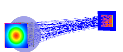
The irradiance profile of the source is a Gaussian with a half width of 5 mm as shown below (created with 100 million rays).

The final distribution after the beam has passed through the homogenizer at the illumination plane (100mm distance) is shown below. As seen from the final distribution at the illumination plane, we have successfully homogenized our beam.

Contact us to request a Demo of FRED or talk through your application needs in more detail.