Stray Light Analysis
Introduction
Stray Light Analysis
Stray light is the presence of unintended, and generally unwanted, light paths in an optical system that become a source of noise in the measured optical signal. These paths can be generated by events such as scattering from optical or mechanical surfaces and ghost paths caused by reflections from nominally transmissive surfaces.
FRED's stray light analysis toolset has been developed over many years to make these paths easier to find and understand, making FRED an indispensable platform for stray light analysis.
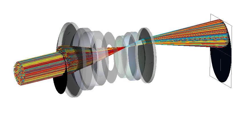
This article highlights several FRED capabilities for simulating and identifying stray light in your system, including:
- Detailed ray trace controls
- How to generate ray paths
- The Raytrace Paths Report
- Filtering with Ray Filters and the 'Analysis Lasso' filter
- The Stray Light Report
Read our 3-part series here
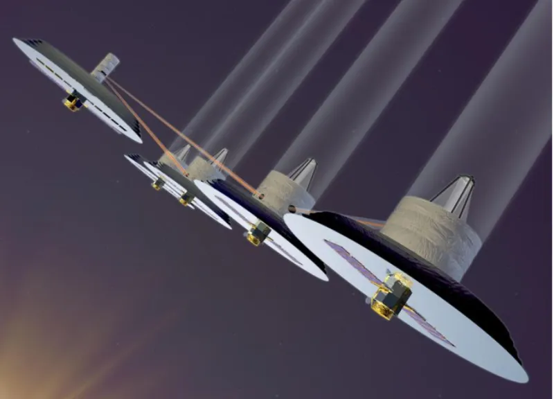
The NASA Terrestrial Planet Finder (TPF)
A space-based telescope concept for detecting planets around stars. It is a multi-telescope interferometric system in which the star image is nulled out, revealing the planet.
As particulate contamination levels increase over time, instrument sensitivity degrades over the operational lifetime of the system.
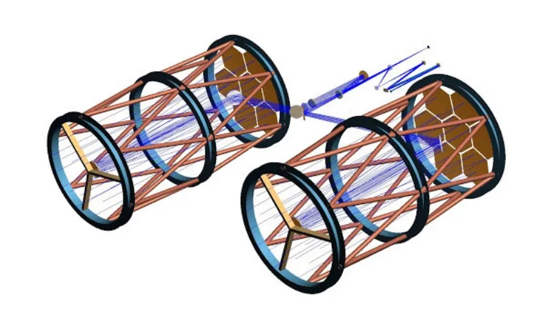
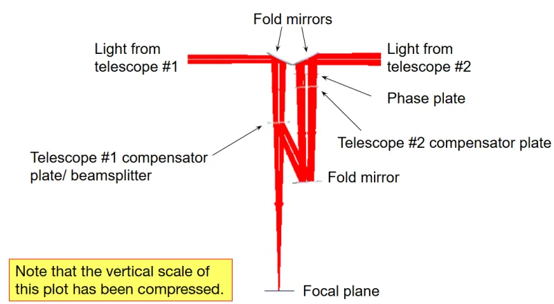
Demonstration of Principle
Left: Simulation model of the system. Light enters from two telescopes, and one path includes a phase plate.
(A): With direct imaging, only the star image is visible.
(B): When the phase plate is adjusted to null the star image, the planet becomes clearly visible.
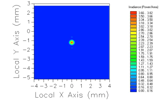
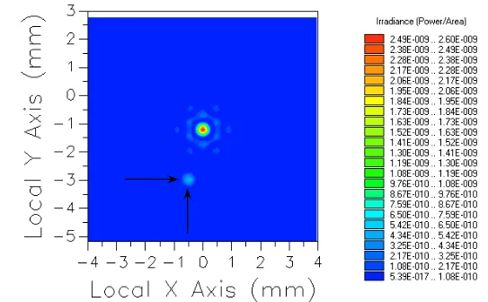
Performance Degradation Due to Scatter
In the actual hardware, at least two scatter mechanisms are present on the primary and secondary mirrors:
Surface roughness:
- 20A rms. Total integrated scatter (TIS) = 0.0006%.
Particulate contamination:
- Mirror surfaces are covered according to the MIL-STD-1246 distribution.
- Two levels were evaluated: CL400 (0.1%) and CL600 (1.0%).
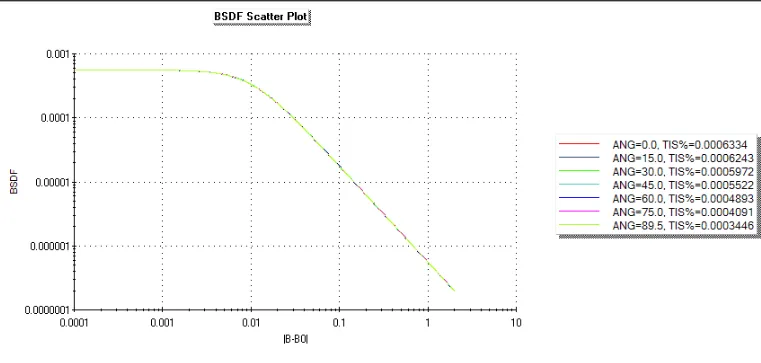
Simulation Results
Observe a planet orbiting a bright star
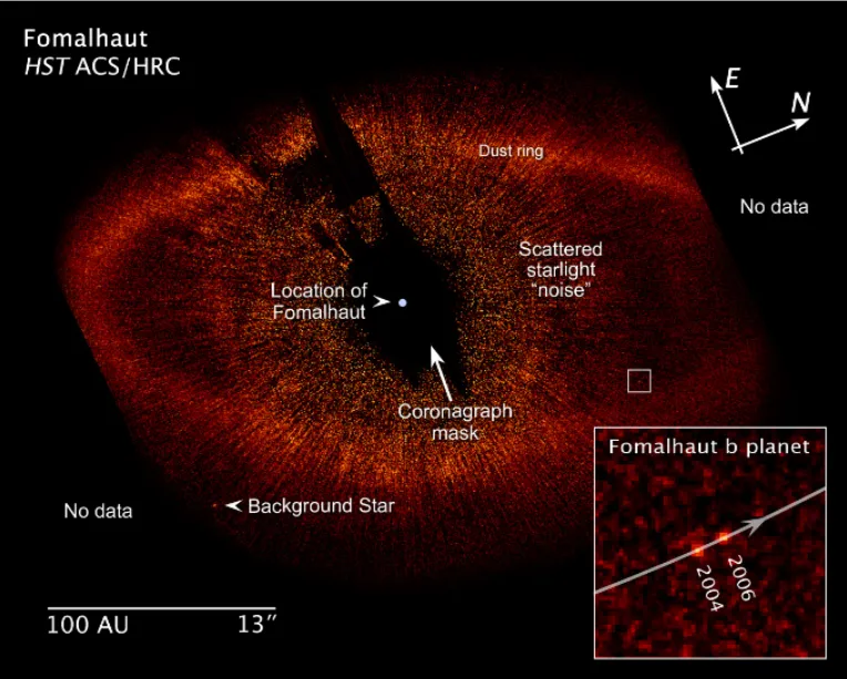
No surface roughness, no contamination
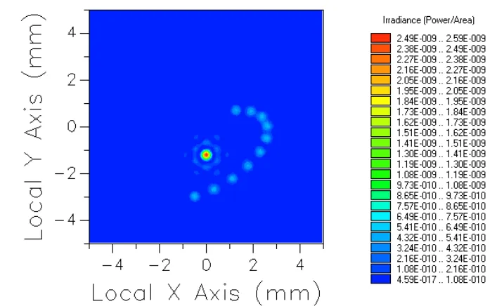
20A rms roughness, 0.1% contamination
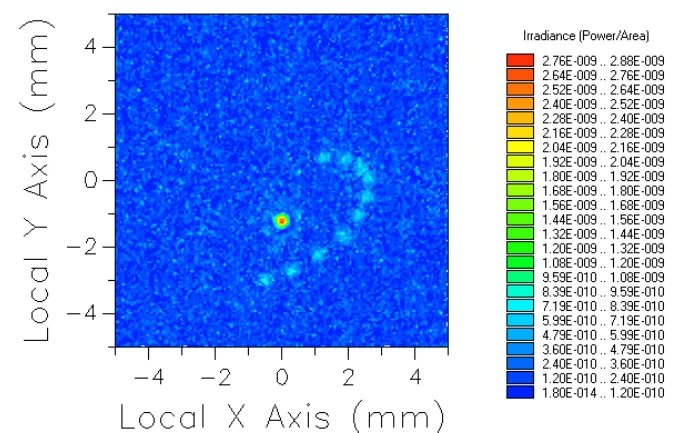
20A rms roughness, 1.0% contamination
Stray Light Analysis of the Large Synoptic Survey Telescope (LSST)
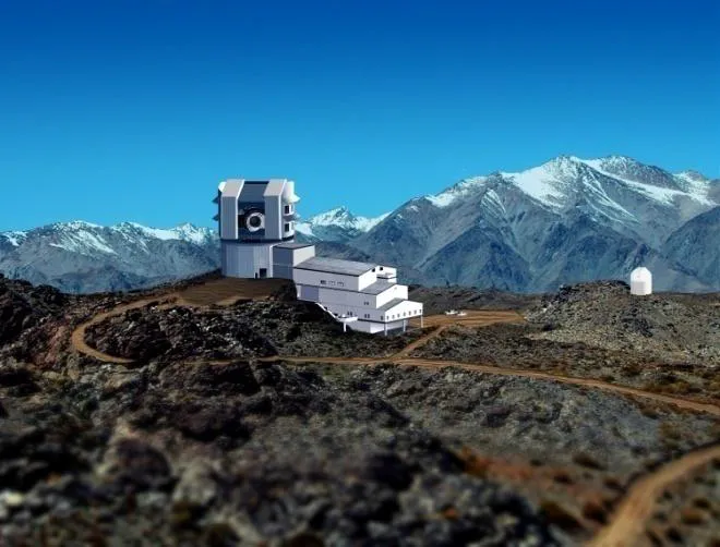
The Large Synoptic Survey Telescope (LSST) at the Rubin Observatory is a large ground-based telescope that can survey the entire sky every three nights to build a detailed map of the universe while searching for faint and moving objects (www.lsst.org).
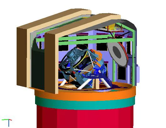
FRED was used to study the initial proposed design and identify stray light mechanisms that required unique baffling approaches.

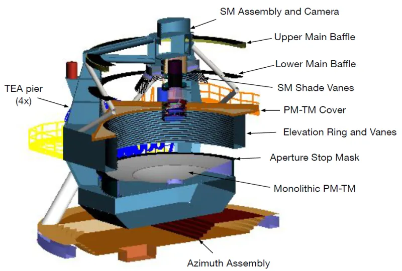
The FRED Optical Model
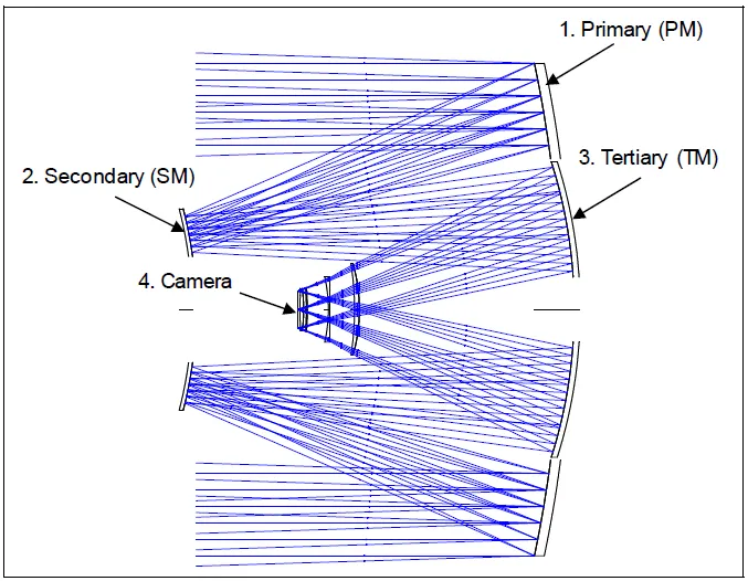
To be effective, computer modeling of telescope systems must be accurate and sufficiently detailed.
In the FRED model, the mirrors use a silver coating with 94% average reflectivity and Harvey-Shack scatter models for surface roughness.

- A Mie particle model was also used for contamination with the EST-STD-1246D distribution model.
- The optical filters use an anti-reflective coating with average reflectivity below 1.5%. The specular reflectivity of the CCD detector is set to 18%.
- Non-optical surfaces were assigned a Black Paint scatter model for Aeroglaze Z306.
Stray Light Analysis Results
"PST" Point Source Transmittance
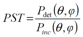
A PST calculation analyzes stray light in a system. It is defined as the total power at the detector divided by the total light entering the system.
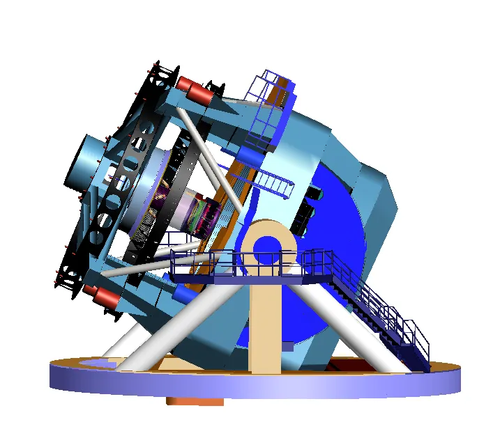
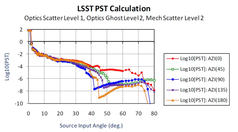
PST was calculated for telescope orientations from 0 to 80 degrees (b) and for five different azimuth angles. The results in (c) showed three distinct causes of stray light.
- (i) 2 - 10 deg: Surface roughness from the primary and secondary mirrors
- (ii) 10 - 40 deg: Scatter from the baffles and other non-optical surfaces
- (iii) 40 - 80 deg: Scatter from the dome above the telescope
About Photon Engineering
Founded in 1997, Photon Engineering is an optical engineering software and consulting firm and the creator of the industry-leading ray tracing software FRED.
CBS is the exclusive Canadian distributor for Photon Engineering's FRED Optical Engineering software.