
Blog
Stray Light Analysis (Part 2)

In part one of our stray light blog we discussed some of the great tools FRED has to calculate and make sense of the stray light in a system. However, it’s not all about calculations, the user interface also plays a large part in how FRED excels at handling complex opto-mechanical systems.
Working with Complex Optical Systems
One of the challenges in stray light analysis is applying and keeping track of all the optics, mechanics, and various surface finishes in the form of coating and scattering functions. As a stray light model is iterated, optical coatings and surface definitions may need to be refined for a system containing many surfaces and parts, and models can become complex very quickly.
FRED’s User Interface has been designed to help cut down on this complexity.
- FRED’s CAD Object Tree definition allows the convenient collection of optics and mechanics in assemblies and sub-assemblies which can be expanded or collapsed as desired.
- FRED makes it simple to refine the properties applied to surfaces via several methods including the drag and drop interface, the assigned pop-up menu item, and the Edit/View All Surfaces table.
- Keywords allow for unconstrained tagging of objects, surfaces, assemblies, and sub-assemblies. Once objects are tagged with a keyword, all the necessary properties, and subsequent refinements can be applied to the keyword and cascade to all tagged items.
- FRED’s isolation feature allows a fast and simple method to focus on objects of interest by temporarily removing other items from view in just a few clicks.
CAD based Object Tree
FRED’s Object Tree neatly sorts the optical system into several easier to manage folders, for sources, geometry, analysis/detectors, materials, etc:
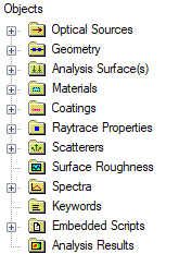
Figure 1 - The Object Tree
The geometry folder can contain subassemblies which can be expanded and collapsed to show as much or as little detail as is required at any stage. For instance, the Geometry could be grouped into two sub-assemblies, one for optics, another for mechanics, and the mechanics folder can itself contain sub-assemblies:
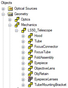
Figure 2 - Object Tree nodes expanded to show subassemblies within the mechanical subassembly
The mechanical components of which can be seen in a cut-away view of the telescope:
Figure 3 - A cutaway of the model showing the optics (yellow) and mechanics (grey)
Easily Refine Properties
FRED provides several approaches to changing optical properties of surfaces.
Drag and Drop
To change an optical property of a single surface the simplest approach is to use the drag and drop functionality. E.g. to change the coating on surface 1 from “QW MgF2” to “2 Layer AR” we just need to click the “2 Layer AR” coating entry and drag it up to Surface 1 and release the mouse button. The new coating is then applied.
Figure 4 - Drag and drop individual properties to a surface
Drag and drop also works on subassemblies and applies the property to everything contained within the subassembly.
Assign Pop-up Menu Option
Where it is required to change coatings and raytrace properties at the same time for a single surface, or a small subset of surfaces, we can use the Assign pop-up menu option. E.g. to change four optical surfaces to use both the “2 Layer AR” coating and the “Allow All” raytrace control we simply select the coating, raytrace control, and surfaces of interest (holding the CTRL key to multi-select) then right-click to invoke the pop-up menu that allows us to assign these properties to the selected surfaces.
Figure 5 - Assign pop-up option to assign a few properties to a small number of surfaces
Multiple Surface Table
Where we need to edit large numbers of surfaces all at once, or just get a general overview of the optical properties currently in use, then it’s more efficient to use the Multiple Surface View / Edit table. This is accessed from Edit then “Edit / View All Surfaces”. In this table we can view or change properties of any number of surfaces up to and including the entire list of surfaces.
Figure 6 - Using the Multiple Surface table to make multiple bulk edits to many surfaces simultaneously.
Inside the Multiple Surface table we can filter the surface list based on if the surface is currently selected , traceable or isolated, and sort the rows by from the column headers before selecting any number of rows to edit.
Keywords
In our simple telescope example the Optics and Mechanics are already separated into two sub-assemblies, but even with this level of grouping already in place the mechanics do not all have the same optical finish. How best to keep control of what properties are used on which components? In this situation, keywords can be used to impose some order.
Keywords facilitate complex model construction and configuration by acting as pass-throughs for objects which have been assigned a keyword. This property type adds an additional level of organization and control over model configuration on top of the basic organizational hierarchy provided by the object tree structure itself. In this case, the mechanics needs to have two different surface finishes, namely those of “Glossy Black Plastic” and “Black Anodized Aluminium”:
Figure 7 - Using keywords as a proxy to assign properties to different surfaces at once
Using keywords makes it simpler to group items by some commonality and then apply changes to the keyword instead which propagate down to the items tagged with that keyword. Note that items can have more than one keyword.
Easily view sub-components within the model
When faced with a complex model sometimes it can help to strip back some of that complexity for a moment, to view a subset of optical surfaces, or mechanics, perhaps to select a few of them for use in tandem with the ‘Selected Surfaces’ filter of the Multiple Surface table seen previously. FRED’s isolation feature was made for this.
Isolation doesn’t just work on single pieces of geometry. We can invoke the isolate feature on groups of surfaces, assemblies, coatings, raytrace controls, and keywords, as shown in the figure below.
Figure 8 - using the isolate feature to examine and interact with the fold mirror assembly, then isolating those components tagged with the “Black Anod Al” keyword.
Summary
FRED’s UI was created and optimized by stray light experts to make it simpler to work with complex opto-mechanical systems when conducting stray light analysis.
Contact us to request a Demo of FRED or talk through your application needs in more detail.